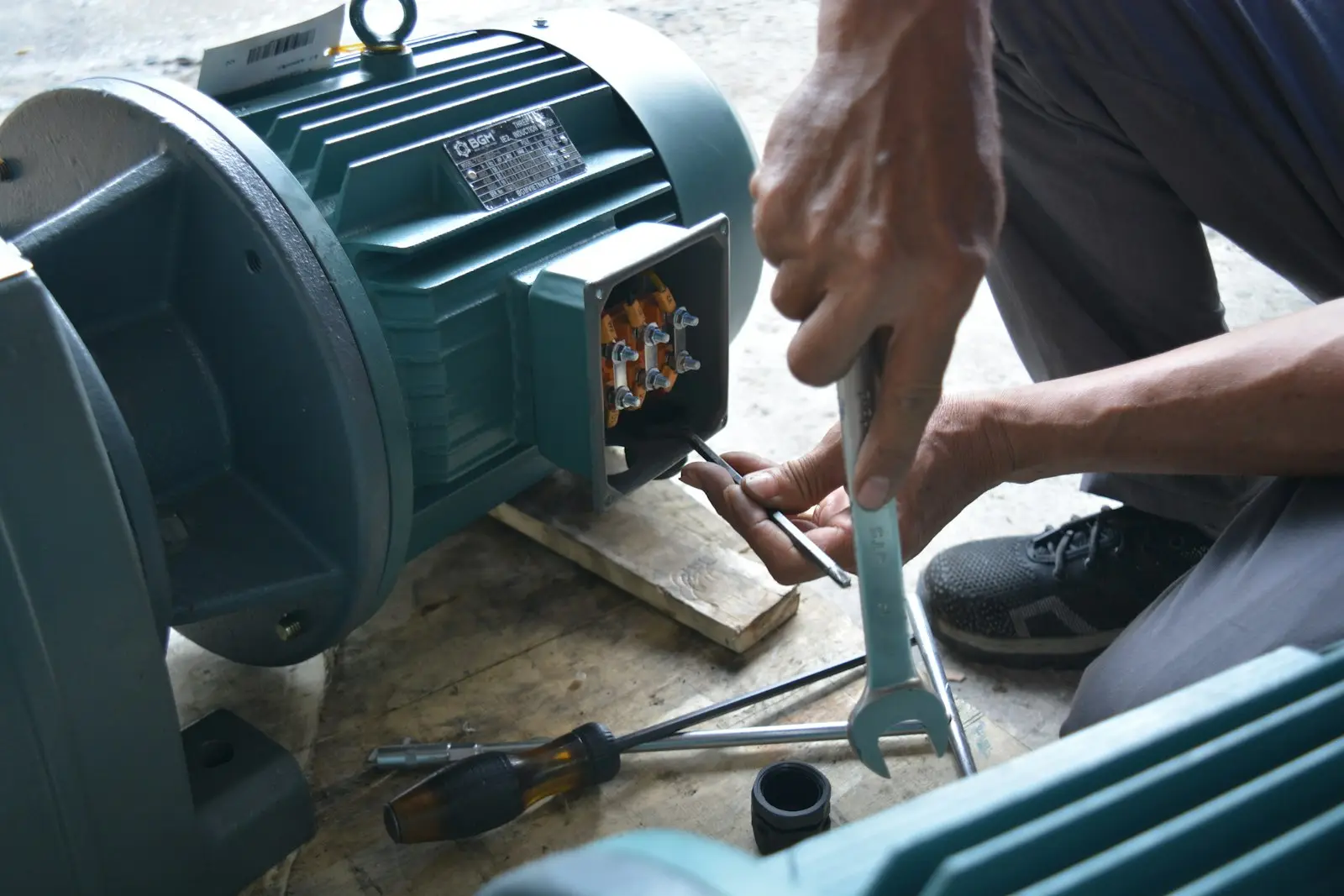
Traditional dial indicator alignment is slow and suffers from bar sag and reading errors. Laser alignment measures offset and angularity directly in both vertical and horizontal planes and calculates corrections at each foot.
Before aligning we check and correct soft foot, calculate shims and apply target values that account for thermal growth at operating temperature.
Benefits
Longer bearing and seal life
Additional radial and axial loads disappear.
Less coupling wear
Elastic elements and gear teeth are protected.
Energy savings
Friction and heat losses from misalignment are reduced.
Documented quality
Before/after values reported against tolerances.
Process
Pre-check
Foundation, bolts, pipe strain and soft foot.
Measurement
Offset and angularity measured with laser sensors.
Correction
Shimming and horizontal moves.
Report
Before/after values against tolerances.
Deliverables
- Soft foot readings
- Before/after offset and angularity
- Shim and move values
- Tolerance assessment
Applications
- Motor-pump sets
- Motor-fan sets
- Motor-gearbox sets
- Compressors
- Generator sets
- Cardan and spacer shafts
Frequently asked questions
How are alignment tolerances determined?
Mainly by running speed: the higher the speed, the smaller the permissible offset and angularity. Industry tolerance tables for the machine's speed — not the coupling manufacturer's allowable misalignment — should be used.