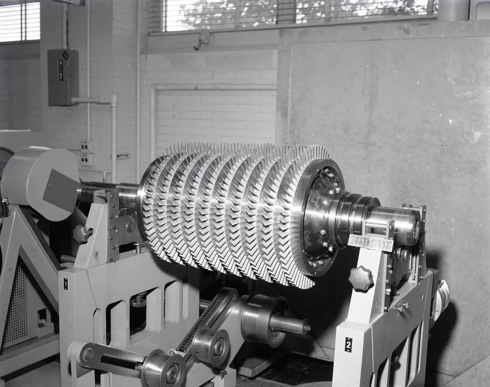
A machine runs hot on one bearing, the 1X line dominates the spectrum, and the crew reaches for the balancing kit. Sometimes that is the right call. Sometimes the real fault is misalignment, and adding weight only hides the symptom. This article shows you how to use spectrum shape, phase readings and orbit data to decide which fault you are facing before you touch the rotor.
Why the two faults look similar at first glance
Unbalance creates a centrifugal force that rotates with the shaft:
F = m · r · ω²
where m is the unbalance mass in kg, r is the distance from the shaft centre to that mass in m, and ω is the angular speed in rad/s. Because the force rotates once per revolution, unbalance shows up as a strong 1X peak — vibration at exactly the running speed frequency.
Misalignment between coupled shafts also forces the rotor off its ideal line. It produces periodic forcing at 1X and, through the coupling's reaction forces, at 2X and sometimes 3X. So both faults raise the 1X line, and a technician who only looks at overall amplitude or the tallest peak cannot tell them apart. The separation comes from three places: the ratio of 1X to 2X, the phase relationship between bearings, and the orbit shape.
What the spectrum says
Start with a spectrum measured in velocity, in mm/s RMS, at each bearing. ISO 20816-3 (and its predecessor ISO 10816-3) gives severity zones for grouping machines, and ISO 17359 sets the condition monitoring framework that tells you when to take these readings.
Typical patterns:
- Unbalance: 1X dominates. 2X is usually below 20 to 30 percent of 1X, though the exact ratio depends on the machine. Harmonics above 2X stay low.
- Misalignment: 2X rises toward or above 1X, especially in the axial direction on the bearing nearest the coupling. 3X may appear. Axial vibration often exceeds half the radial vibration — a ratio that pure unbalance rarely produces.
- Looseness, a frequent misalignment consequence: a forest of harmonics at 1X, 2X, 3X and beyond, sometimes with subharmonics at 0.5X.
Check the axial readings specifically. Unbalance is a radial force; it produces little axial vibration unless the rotor is loose on its shaft or a resonant amplification is at work. Strong axial 1X and 2X near the coupling points at the shaft line, not at the mass distribution.
You can compare your measured spectrum against reference fault patterns in the Vibration Fault Spectrum Simulator and convert between displacement, velocity and acceleration units with the Vibration Unit Converter when your data collector reports in different units.
What phase tells you
Phase is the strongest discriminator, and it is where most field crews stop too early. You need a once-per-revolution reference: an optical or laser tachometer on a reflective tape, or a keyphasor pulse.
Measure 1X phase at each bearing, in both horizontal and vertical directions. Then apply these rules:
- Same phase, horizontal vs vertical, on one bearing (within roughly ±30°): suspect a bowed shaft or a pre-load condition rather than simple unbalance.
- Steady 90° phase difference between horizontal and vertical on one bearing: consistent with unbalance, because the rotating force sweeps past each probe a quarter turn apart. The sign (H leads V or V leads H) tells you the direction of rotation.
- Phase difference close to 180° across the coupling — for example, one coupling-side bearing reads 40° and the mating bearing reads 220°: the two shafts are moving in opposition. This is a classic misalignment signature.
- Phase difference close to 0° or 180° between the two bearings on the same rotor: 0° suggests static (parallel) unbalance, 180° suggests couple unbalance. Decompose the two with the Static and Couple Unbalance Decomposition method before choosing single- or two-plane correction.
Phase must be repeatable. Take three readings at each point. If phase wanders more than about ±20° between readings, the machine is unstable or the tachometer trigger is unreliable — fix the measurement first, because no balancing or alignment decision is safe on unstable phase.
The orbit and time waveform check
If you have a two-channel analyser with XY probes on a sleeve-bearing machine, plot the orbit.
- Unbalance: a smooth, roughly elliptical orbit, forward precession, centred in the bearing clearance.
- Misalignment: a flattened or banana-shaped orbit, sometimes with an inner loop, and precession that may go backward at some speeds.
- Severe misalignment or looseness: clipped or figure-eight orbits.
On rolling-element machines without shaft probes, use the time waveform. Unbalance gives a clean sinusoid at 1X. Misalignment adds a distorted, flattened waveform with visible 2X content. ISO 13373 describes these measurement and analysis procedures in detail, and ISO 18436 defines the personnel certification levels for the analyst performing them.
You can build intuition for orbit shapes on the Shaft Orbit Simulator and study how 1X and 2X components combine in the Time Waveform and FFT Spectrum Simulator.
A field procedure you can follow
Run this sequence before deciding on correction:
- Record the machine speed and confirm the tachometer reads a stable 1X frequency. Note the units: frequency in Hz equals speed in rpm divided by 60.
- Take spectra in velocity (mm/s RMS) at each bearing, horizontal, vertical and axial. Use enough resolution to separate 1X and 2X — a window covering at least 10 orders of the running speed works for most machines.
- Compare 2X to 1X at each bearing. Note where 2X is highest and whether it is axial.
- Measure 1X phase at every bearing with a reference tachometer. Take three readings per point and check repeatability within ±20°.
- Compute phase differences: across the coupling, and horizontal-versus-vertical at each bearing.
- If available, capture an orbit or a time waveform.
- Decide:
- 1X dominant, 2X low, 90° H/V split, phase consistent around the rotor → treat as unbalance. Set the tolerance per ISO 21940-11 (which replaced ISO 1940-1) using the ISO 21940-11 Balance Tolerance Calculator, then correct in the field — see Field Balancing (On-Site Dynamic Balancing).
- High 2X, especially axial, 180° phase across the coupling, distorted orbit → treat as misalignment. Align first, then re-measure. Alignment tolerances depend on speed and coupling type; the Shaft Alignment Tolerances page lists them, and the Shaft Alignment Calculator: Face-Rim and Reverse Indicator supports the indicator methods.
- Mixed picture → correct alignment first, re-measure, then balance the residual. Alignment changes the 1X response, so balancing before aligning wastes a trim run.
ISO 21940-14 covers balancing errors and their evaluation, ISO 21940-21 describes rotor balancing on machines with flexible behaviour, and ISO 14694 sets vibration limits for balancing machines themselves. If the 1X amplitude changes with speed and peaks near a known critical speed, resonance is amplifying the unbalance response — confirm with the Resonance & Critical Speed Simulator before planning correction runs.
When the picture stays unclear
Some machines refuse to fit either pattern: overhung rotors reverse the phase logic, belt drives add tension forces, and a cracked shaft can mimic misalignment with its abnormal 1X phase behaviour between bearings. If phase is unstable, 2X and 1X are both high, or two correction attempts have not brought the machine inside its ISO 20816-3 zone, stop guessing. An on-site measurement with a multi-channel 24-bit system captures simultaneous phase-referenced data at all bearings in one run, which removes the trial-and-error. Request a measurement through /en/contact — bring your spectra, phase table and machine speed history, and the diagnosis usually takes one visit.